In mineral processing and aggregate washing plants, solid-liquid separation is a critical step that bridges wet beneficiation circuits with final concentrate dewatering or tailings disposal. While upstream grinding and flotation determine mineral liberation and grade, the performance of downstream dewatering equipment depends heavily on proper thickener selection and sizing.
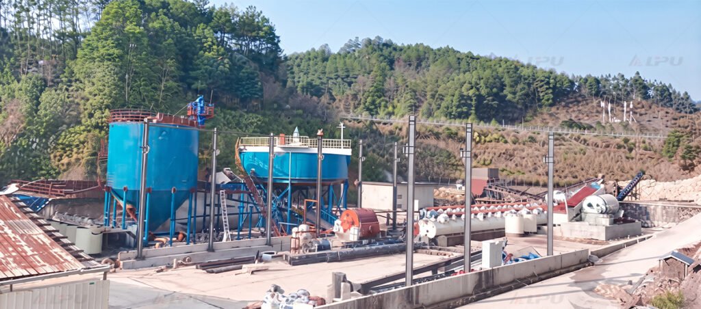
Integrated conditioning and thickening systems configured for continuous mineral processing circuits.
A high-performance thickening system does more than simply clarify water; it ensures stable underflow density, protects downstream filtration equipment, and maximizes water recycling efficiency across the plant.
This guide outlines the engineering parameters required to select and configure a mineral thickener, covering tank sizing, feed preparation, drive mechanisms, underflow management, and layout considerations.
1. What is the core role of a thickener in the beneficiation circuit?
In a continuous mineral processing circuit, slurries exiting flotation cells, magnetic separators, or classification stages typically have low solids concentrations (often 10% to 30% solids by weight). Pumping these dilute slurries directly to filters is economically and operationally impractical.
Thickeners play a dual role in the beneficiation circuit by recovering clean process water and densifying slurry solids for downstream handling
Clarification: Capturing suspended fine particles to produce clear overflow water that can be immediately recycled back to the grinding or washing circuit.
Densification: Settling and compacting slurry solids via gravity to achieve a high-density underflow suitable for pumping.
Buffer Storage: Providing surge capacity between continuous wet beneficiation operations and intermittent dewatering units.
2. Differentiating concentrate thickening, tailings thickening, and water recovery
Not all thickeners perform the same duty. Equipment configuration varies significantly based on the application:
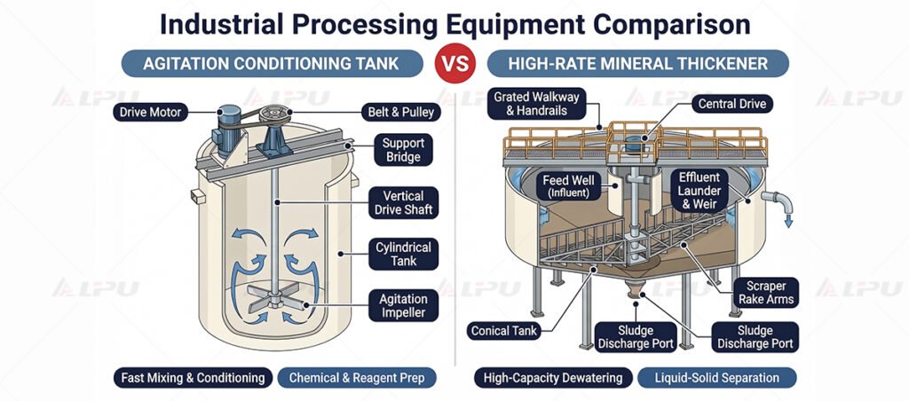
Side-by-side comparison of agitation conditioning tanks and mineral thickeners
Concentrate Thickening: Focuses on upgrading valuable mineral slurry (such as copper, gold, or iron concentrate) prior to filtration. The emphasis is on preventing contamination, achieving moderate-to-high underflow density, and capturing every fine particle of value.
Tailings Thickening: Focuses on high-volume throughput and maximum water recovery from waste slurry. Tailings thickeners are typically large-diameter units designed to handle variable mineralogy and produce a dense underflow for surface dry stacking or tailings dam disposal.
Water Clarification & Recirculation: Tailored for process water circuits where solid loading is relatively low, prioritizing maximum clear-water overflow rates and minimum suspended solids.
3. Determining tank diameter using settling tests and settling area
Sizing a thickener tank requires laboratory dynamic settling tests (such as Coe-Ciborowski or Talmadge-Fitch methods) performed on representative slurry samples.
Unit Area Calculation: Laboratory batch settling tests determine the settling velocity of the slurry interface over time. The required settling area (A) is calculated based on mass flow rate and the limiting settling flux.
Tank Diameter Derivation: Once the required surface area is established, the tank diameter (D) is calculated using standard circular geometry (A=πD2/4).
Compaction and Compression Zone: Beyond surface area for free settling, deep-tank or high-rate designs provide adequate sidewall height to ensure the lower compression zone densifies the settled solids to the target underflow percentage.
4. Matching feed wells, flocculation conditions, and clarity requirements
Modern high-rate thickeners rely heavily on advanced feed well design to optimize chemical mixing and flocculation.
Flocculant Dispersion: Polymer flocculants (such as polyacrylamides) must be gently and thoroughly mixed with the incoming slurry inside the feed well to agglomerate fine particles into fast-settling flocs.
Energy Dissipation: The feed well must dissipate the kinetic energy of the incoming slurry stream without generating high-shear turbulence that can break fragile flocs.
Overflow Clarity: Optimizing feed well residence time and baffling prevents short-circuiting, ensuring suspended solids remain below threshold limits in the overflow launder.
5. Selecting rake mechanisms, center drives, and torque protection
The rake mechanism and drive head are the mechanical heart of the thickener, responsible for moving settled solids toward the central discharge cone.
Rake Blade Configuration: Truss-type or solid-plate rake arms equipped with plow blades gently push settled solids inward along the tank bottom without causing excessive bed disturbance.
Center Drive Mechanism: High-torque center drive units handle heavy underflow bed loads. Planetary gearboxes and variable-speed drives provide smooth, continuous rotation.
Torque Protection & Auto-Lift: To prevent catastrophic structural failure when solids pack or stall in the tank, thickener drives feature automatic torque-sensing overload alarms and motorized rake-lifting devices that raise the rakes above high-density sludge layers.
6. Designing underflow density, discharge cones, and pump interfaces
The bottom design dictates how efficiently densified slurry exits the thickener.
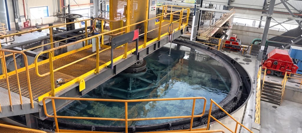
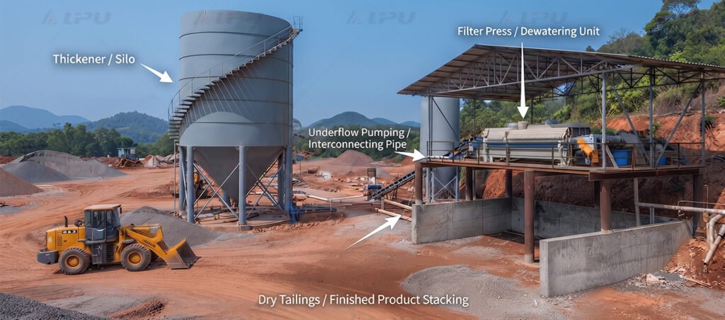
Thickened underflow is pumped into plate filter presses for secondary dewatering
Underflow Concentration: Target solids concentration must balance pumpability with downstream requirements. Over-thickened slurry can cause line plugging or torque spikes.
Discharge Cone Geometry: Stepped or sloped cone bottoms with flushing connections prevent particle settling dead-zones and bridging.
Pump and Filter Press Integration: Underflow slurry is typically extracted using heavy-duty slurry pumps and fed into secondary dewatering units such as a Plate Filter Press to achieve dry cake stacking. Pipe diameters and valving must accommodate non-Newtonian shear-thinning slurry rheology.
7. Checking overflow launders, recycle piping, and maintenance access
Plant layout and auxiliary infrastructure ensure safe, continuous operation.
Overflow Launder Design: V-notch weir plates installed around the perimeter ensure even liquid draw-off and prevent localized surging across the tank surface.
Recycle Piping Routing: Clear overflow water flows by gravity into a header tank or directly back to grinding mills and wash water pumps.
Access Walkways and Maintenance: Overhead bridges provide safe access to the center drive mechanism, flocculant addition points, and feed well inspection hatches.
8. Essential slurry and process data required before equipment quotation
To receive an accurate thickener design and commercial proposal, plant operators should provide equipment manufacturers with comprehensive data:
Solid and Liquid Characteristics: Specific gravity of solids and liquid phase, mineral composition, and particle size distribution (P80).
Mass Flow Rates: Dry solids feed rate (tph) and volumetric slurry flow rate (m3/h).
Slurry Conditions: Operating pH, temperature, chemical additives, and presence of hydrocarbons or sticky clays.
Performance Targets: Required overflow clarity (TSS in mg/L) and target underflow solids concentration (% by weight).
Site Conditions: Elevation, seismic zone, ambient temperature range, and available power supply.
Frequently Asked Questions
What is the main difference between a conventional thickener and a high-rate thickener? A conventional thickener relies primarily on natural gravity settling with minimal chemical addition, requiring large tank diameters. A high-rate thickener incorporates an advanced feed well for polymer flocculant dosing, accelerating particle aggregation and allowing significantly higher solid loading rates within a smaller footprint.
How is the required thickener diameter determined from lab tests? Lab settling tests generate settling velocity curves at various initial pulp densities. By calculating the limiting solids flux and mass input, engineers determine the required unit area. The tank diameter is then derived mathematically to ensure the surface area meets or exceeds this critical value.
What causes a thickener rake to stall, and how is it prevented? Rake stalls occur when high-density solids accumulate in the tank bottom, exceeding the drive motor’s torque limit. This is prevented by installing high-torque gearboxes, torque-monitoring alarms, and pneumatic or motorized rake-lifting devices that raise the arms above the sludge bed during power outages or high-load surges.
Can thickener underflow be fed directly to a plate filter press? Yes, in many mineral processing plants, thickener underflow is pumped into a surge agitator before being fed at high pressure into a Plate Filter Press to produce dry filter cakes for transport or dry stacking.
What information should I provide to get an accurate thickener recommendation? Provide your dry solids feed rate (tph), slurry solid SG, feed solids concentration (% by weight), target underflow density, required overflow water clarity, and any available mineralogical or settling test data. Contact our engineering team to discuss your solid-liquid separation requirements.
We will reply to you within 24 hours